Network Models & IP Address
Network Models
A communication subsystem is a complex piece of Hardware and software. Early attempts for implementing the software for such subsystems were based on a single, complex, unstructured program with many interacting components. The resultant software was very difficult to test and modify. To overcome such problem, the ISO has developed a layered approach. In a layered approach, networking concept is divided into several layers, and each layer is assigned a particular task. Therefore, we can say that networking tasks depend upon the layers.
Layered Architecture
The main aim of the layered architecture is to divide the design into small pieces.
Each lower layer adds its services to the higher layer to provide a full set of services to manage communications and run the applications.
It provides modularity and clear interfaces, i.e., provides interaction between subsystems.
It ensures the independence between layers by providing the services from lower to higher layer without defining how the services are implemented. Therefore, any modification in a layer will not affect the other layers.
The number of layers, functions, contents of each layer will vary from network to network. However, the purpose of each layer is to provide the service from lower to a higher layer and hiding the details from the layers of how the services are implemented.
The basic elements of layered architecture are services, protocols, and interfaces.
Service: It is a set of actions that a layer provides to the higher layer.
Protocol: It defines a set of rules that a layer uses to exchange the information with peer entity. These rules mainly concern about both the contents and order of the messages used.
Interface: It is a way through which the message is transferred from one layer to another layer.
In a layer n architecture, layer n on one machine will have a communication with the layer n on another machine and the rules used in a conversation are known as a layer-n protocol.

Why do we require Layered architecture?
Divide-and-conquer approach: Divide-and-conquer approach makes a design process in such a way that the unmanageable tasks are divided into small and manageable tasks. In short, we can say that this approach reduces the complexity of the design.
Modularity: Layered architecture is more modular. Modularity provides the independence of layers, which is easier to understand and implement.
Easy to modify: It ensures the independence of layers so that implementation in one layer can be changed without affecting other layers.
Easy to test: Each layer of the layered architecture can be analyzed and tested individually.
OSI MODEL
1. OSI stands for Open System Interconnection is a reference model that describes how information from a software application in one computer moves through a physical medium to the software application in another computer.
2. OSI consists of seven layers, and each layer performs a particular network function.
3. OSI model was developed by the International Organization for Standardization (ISO) in 1984, and it is now considered as an architectural model for the inter-computer communications.
4. OSI model divides the whole task into seven smaller and manageable tasks. Each layer is assigned a particular task.
5. Each layer is self-contained, so that task assigned to each layer can be performed independently.

Characteristics of OSI Model
1) The OSI model is divided into two layers: upper layers and lower layers.
2) The upper layer of the OSI model mainly deals with the application related issues, and they are implemented only in the software. The application layer is closest to the end user. Both the end user and the application layer interact with the software applications. An upper layer refers to the layer just above another layer.
3) The lower layer of the OSI model deals with the data transport issues. The data link layer and the physical layer are implemented in hardware and software. The physical layer is the lowest layer of the OSI model and is closest to the physical medium. The physical layer is mainly responsible for placing the information on the physical medium.
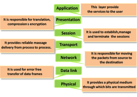
PHYSICAL LAYER
The lowest layer of the OSI reference model is the physical layer. It is responsible for the actual physical connection between the devices. The physical layer contains information in the form of bits. It is responsible for transmitting individual bits from one node to the next. When receiving data, this layer will get the signal received and convert it into 0s and 1s and send them to the Data Link layer, which will put the frame back together.
The functions of the physical layer are as follows:
Bit synchronization: The physical layer provides the synchronization of the bits by providing a clock. This clock controls both sender and receiver thus providing synchronization at bit level.
Bit rate control: The Physical layer also defines the transmission rate i.e. the number of bits sent per second.
Physical topologies: Physical layer specifies the way in which the different, devices/nodes are arranged in a network i.e. bus, star, or mesh topology.
Transmission mode: Physical layer also defines the way in which the data flows between the two connected devices. The various transmission modes possible are Simplex, half-duplex and full-duplex.
DATA LINK LAYER(DLL0 — LAYER 2
The data link layer is responsible for the node-to-node delivery of the message. The main function of this layer is to make sure data transfer is error-free from one node to another, over the physical layer. When a packet arrives in a network, it is the responsibility of DLL to transmit it to the Host using its MAC address.
Data Link Layer is divided into two sublayers:
1. Logical Link Control (LLC)
2. Media Access Control (MAC)
The packet received from the Network layer is further divided into frames depending on the frame size of NIC(Network Interface Card). DLL also encapsulates Sender and Receiver’s MAC address in the header.
The Receiver’s MAC address is obtained by placing an ARP(Address Resolution Protocol) request onto the wire asking “Who has that IP address?” and the destination host will reply with its MAC address.
The functions of the Data Link layer are :
Framing: Framing is a function of the data link layer. It provides a way for a sender to transmit a set of bits that are meaningful to the receiver. This can be accomplished by attaching special bit patterns to the beginning and end of the frame.
Physical addressing: After creating frames, the Data link layer adds physical addresses (MAC address) of the sender and/or receiver in the header of each frame.
Error control: Data link layer provides the mechanism of error control in which it detects and retransmits damaged or lost frames.
Flow Control: The data rate must be constant on both sides else the data may get corrupted thus, flow control coordinates the amount of data that can be sent before receiving acknowledgement.
Access control: When a single communication channel is shared by multiple devices, the MAC sub-layer of the data link layer helps to determine which device has control over the channel at a given time.
NETWORK LAYER — LAYER 3
The network layer works for the transmission of data from one host to the other located in different networks. It also takes care of packet routing i.e. selection of the shortest path to transmit the packet, from the number of routes available. The sender & receiver’s IP addresses are placed in the header by the network layer.
The functions of the Network layer are :
Routing: The network layer protocols determine which route is suitable from source to destination. This function of the network layer is known as routing.
Logical Addressing: In order to identify each device on internetwork uniquely, the network layer defines an addressing scheme. The sender & receiver’s IP addresses are placed in the header by the network layer. Such an address distinguishes each device uniquely and universally.
TRANSPORT LAYER — LAYER 4
The transport layer provides services to the application layer and takes services from the network layer. The data in the transport layer is referred to as Segments. It is responsible for the End to End Delivery of the complete message. The transport layer also provides the acknowledgement of the successful data transmission and re-transmits the data if an error is found.
At sender’s side: Transport layer receives the formatted data from the upper layers, performs Segmentation, and also implements Flow & Error control to ensure proper data transmission. It also adds Source and Destination port numbers in its header and forwards the segmented data to the Network Layer.
Generally, this destination port number is configured, either by default or manually. For example, when a web application makes a request to a web server, it typically uses port number 80, because this is the default port assigned to web applications. Many applications have default ports assigned.
At receiver’s side: Transport Layer reads the port number from its header and forwards the Data which it has received to the respective application. It also performs sequencing and reassembling of the segmented data.
The functions of the transport layer are as follows:
Segmentation and Reassembly: This layer accepts the message from the (session) layer, and breaks the message into smaller units. Each of the segments produced has a header associated with it. The transport layer at the destination station reassembles the message.
Service Point Addressing: In order to deliver the message to the correct process, the transport layer header includes a type of address called service point address or port address. Thus by specifying this address, the transport layer makes sure that the message is delivered to the correct process.
The services provided by the transport layer :
A. Connection-Oriented Service: It is a three-phase process that includes
– Connection Establishment
– Data Transfer
– Termination / disconnection
In this type of transmission, the receiving device sends an acknowledgement, back to the source after a packet or group of packets is received. This type of transmission is reliable and secure.
B. Connectionless service: It is a one-phase process and includes Data Transfer. In this type of transmission, the receiver does not acknowledge receipt of a packet. This approach allows for much faster communication between devices. Connection-oriented service is more reliable than connectionless Service.
* Data in the Transport Layer is called as Segments.
** Transport layer is operated by the Operating System. It is a part of the OS and communicates with the Application Layer by making system calls.
Transport Layer is called as Heart of OSI model.
SESSION LAYER-LAYER 5
This layer is responsible for the establishment of connection, maintenance of sessions, authentication, and also ensures security.
The functions of the session layer are :
Session establishment, maintenance, and termination: The layer allows the two processes to establish, use and terminate a connection.
Synchronization: This layer allows a process to add checkpoints which are considered synchronization points into the data. These synchronization points help to identify the error so that the data is re-synchronized properly, and ends of the messages are not cut prematurely and data loss is avoided.
Dialog Controller: The session layer allows two systems to start communication with each other in half-duplex or full-duplex.
**All the below 3 layers(including Session Layer) are integrated as a single layer in the TCP/IP model as “Application Layer”.
**Implementation of these 3 layers is done by the network application itself. These are also known as Upper Layers or Software Layers.
Scenario:
Let us consider a scenario where a user wants to send a message through some Messenger application running in his browser. The “Messenger” here acts as the application layer which provides the user with an interface to create the data. This message or so-called Data is compressed, encrypted (if any secure data), and converted into bits (0’s and 1’s) so that it can be transmitted.

PRESENTATION LAYER-LAYER 6
The presentation layer is also called the Translation layer. The data from the application layer is extracted here and manipulated as per the required format to transmit over the network.
The functions of the presentation layer are :
Translation: For example, ASCII to EBCDIC.
Encryption/ Decryption: Data encryption translates the data into another form or code. The encrypted data is known as the ciphertext and the decrypted data is known as plain text. A key value is used for encrypting as well as decrypting data.
Compression: Reduces the number of bits that need to be transmitted on the network.
APPLICATION LAYER-LAYER 7
At the very top of the OSI Reference Model stack of layers, we find the Application layer which is implemented by the network applications. These applications produce the data, which has to be transferred over the network. This layer also serves as a window for the application services to access the network and for displaying the received information to the user.
Example: Application — Browsers, Skype Messenger, etc.
The functions of the Application layer are :
Network Virtual Terminal
FTAM-File transfer access and management
Mail Services
Directory Services
NOTES:
* Hub, Repeater, Modem, Cables are Physical Layer devices.
** Network Layer, Data Link Layer, and Physical Layer are also known as Lower Layers or Hardware Layers.
* Packet in Data Link layer is referred to as Frame.
** Data Link layer is handled by the NIC (Network Interface Card) and device drivers of host machines.
*** Switch & Bridge are Data Link Layer devices.
* Segment in Network layer is referred to as Packet.
** Network layer is implemented by networking devices such as routers.
Note: In transport layer,The sender needs to know the port number associated with the receiver’s application.
**Application Layer is also called Desktop Layer.
***example for session layer IS NETBIOS protocol
OSI model acts as a reference model and is not implemented on the Internet because of its late invention. The current model being used is the TCP/IP model.
OSI model in a nutshell

ARPANET LOGICAL MAP

TCP/IP Model
The OSI Model we just looked at is just a reference/logical model. It was designed to describe the functions of the communication system by dividing the communication procedure into smaller and simpler components. But when we talk about the TCP/IP model, it was designed and developed by Department of Defense (DoD) in 1960s and is based on standard protocols. It stands for Transmission Control Protocol/Internet Protocol. The TCP/IP model is a concise version of the OSI model. It contains four layers, unlike seven layers in the OSI model. The layers are:
Process/Application Layer
Host-to-Host/Transport Layer
Internet Layer
Network Access/Link Layer
The diagrammatic comparison of the TCP/IP and OSI model is as follows

Difference between TCP/IP and OSI Model


The first layer is the Process layer on the behalf of the sender and Network Access layer on the behalf of the receiver. During this article, we will be talking on the behalf of the receiver.
1. Network Access Layer –
This layer corresponds to the combination of Data Link Layer and Physical Layer of the OSI model. It looks out for hardware addressing and the protocols present in this layer allows for the physical transmission of data.
We just talked about ARP being a protocol of Internet layer, but there is a conflict about declaring it as a protocol of Internet Layer or Network access layer. It is described as residing in layer 3, being encapsulated by layer 2 protocols.
2. Internet Layer –
This layer parallels the functions of OSI’s Network layer. It defines the protocols which are responsible for logical transmission of data over the entire network. The main protocols residing at this layer are :
IP — stands for Internet Protocol and it is responsible for delivering packets from the source host to the destination host by looking at the IP addresses in the packet headers. IP has 2 versions:
IPv4 and IPv6. IPv4 is the one that most of the websites are using currently. But IPv6 is growing as the number of IPv4 addresses are limited in number when compared to the number of users.
ICMP — stands for Internet Control Message Protocol. It is encapsulated within IP datagrams and is responsible for providing hosts with information about network problems.
ARP — stands for Address Resolution Protocol. Its job is to find the hardware address of a host from a known IP address. ARP has several types: Reverse ARP, Proxy ARP, Gratuitous ARP and Inverse ARP.
3. Host-to-Host Layer –
This layer is analogous to the transport layer of the OSI model. It is responsible for end-to-end communication and error-free delivery of data. It shields the upper-layer applications from the complexities of data. The two main protocols present in this layer are :
Transmission Control Protocol (TCP) — It is known to provide reliable and error-free communication between end systems. It performs sequencing and segmentation of data. It also has acknowledgment feature and controls the flow of the data through flow control mechanism. It is a very effective protocol but has a lot of overhead due to such features. Increased overhead leads to increased cost.
User Datagram Protocol (UDP) — On the other hand does not provide any such features. It is the go-to protocol if your application does not require reliable transport as it is very cost-effective. Unlike TCP, which is connection-oriented protocol, UDP is connectionless.
4. Application Layer –
This layer performs the functions of top three layers of the OSI model: Application, Presentation and Session Layer. It is responsible for node-to-node communication and controls user-interface specifications. Some of the protocols present in this layer are: HTTP, HTTPS, FTP, TFTP, Telnet, SSH, SMTP, SNMP, NTP, DNS, DHCP, NFS, X Window, LPD. Have a look at Protocols in Application Layer for some information about these protocols. Protocols other than those present in the linked article are :
HTTP and HTTPS — HTTP stands for Hypertext transfer protocol. It is used by the World Wide Web to manage communications between web browsers and servers. HTTPS stands for HTTP-Secure. It is a combination of HTTP with SSL(Secure Socket Layer). It is efficient in cases where the browser need to fill out forms, sign in, authenticate and carry out bank transactions.
SSH — SSH stands for Secure Shell. It is a terminal emulations software similar to Telnet. The reason SSH is more preferred is because of its ability to maintain the encrypted connection. It sets up a secure session over a TCP/IP connection.
NTP — NTP stands for Network Time Protocol. It is used to synchronize the clocks on our computer to one standard time source. It is very useful in situations like bank transactions. Assume the following situation without the presence of NTP. Suppose you carry out a transaction, where your computer reads the time at 2:30 PM while the server records it at 2:28 PM. The server can crash very badly if it’s out of sync.
What is Data Encapsulation and de-encapsulation in networking?
Whenever we send the data from one node to another in a computer network. The data is encapsulated at the sender’s side, while it is de-encapsulated at the receiver’s end. Actually, the encapsulation of data at various layers of the implementing model(OSI or TCP/IP) adds various functionalities and features to the data transmission. The most important feature that it adds is the security and reliability of data transmission between two nodes in a network.
In this , we will mainly learn what is encapsulation. We will also learn the encapsulation and de-encapsulation process in the OSI and TCP/IP models in detail. So, now let us learn these things one by one.
Data Encapsulation
Data Encapsulation is the process in which some extra information is added to the data item to add some features to it. We use either the OSI or the TCP/IP model in our network, and the data transmission takes place through various layers in these models. Data encapsulation adds the protocol information to the data so that data transmission can take place in a proper way. This information can either be added in the header or the footer of the data.
The data is encapsulated on the sender’s side, starting from the application layer to the physical layer. Each layer takes the encapsulated data from the previous layer and adds some more information to encapsulate it and some more functionalities with the data. These functionalities may include proper data sequencing, error detection and control, flow control, congestion control, routing information, etc.
Data De-encapsulation
Data De-encapsulation is the reverse process of data encapsulation. The encapsulated information is removed from the received data to obtain the original data. This process takes place at the receiver’s end. The data is de-encapsulated at the same layer at the receiver’s end to the encapsulated layer at the sender’s end. The added header and trailer information are removed from the data in this process.
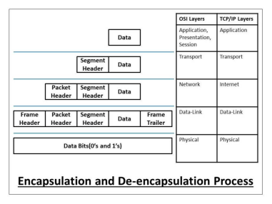
The below diagram shows how header and footer are added and removed from the data in the process of encapsulation and de-encapsulation respectively.

The data is encapsulated in every layer at the sender’s side and also de-encapsulated in the same layer at the receiver’s end of the OSI or TCP/IP model. Actually, we use different terms for the encapsulated form of the data that is described in the below-mentioned diagram.

Now, we will learn the whole process of encapsulation and de-encapsulation in the OSI and TCP/IP model step-by-step as mentioned in the below picture.
Encapsulation Process (At sender’s side)
Step 1: The Application, Presentation, and Session layer in the OSI model, or the Application layer in the TCP/IP model takes the user data in the form of data streams, encapsulates it and forwards the data to the Transport layer. It does not necessarily add any header or footer to the data. But it is application-specific and can add the header if needed.
Step 2: The Transport layer (in the OSI or TCP/IP model) takes the data stream from the upper layers, and divide it into multiple pieces. The Transport layer encapsulates the data by adding the appropriate header to each piece. These data pieces are now called as data segments. The header contains the sequencing information so that the data segments can be reassembled at the receiver’s end.
Step 3: The Network layer (in the OSI model) or the Internet layer (in the TCP/IP model) takes the data segments from the Transport layer and encapsulate it by adding an additional header to the data segment. This data header contains all the routing information for the proper delivery of the data. Here, the encapsulated data is termed as a data packet or datagram.
Step 4: The Data-Link layer (in the OSI or TCP/IP model) takes the data packet or datagram from the Network layer and encapsulate it by adding an additional header and footer to the data packet or datagram. The header contains all the switching information for the proper delivery of the data to the appropriate hardware components, and the trailer contains all the information related to error detection and control. Here, the encapsulated data is termed as a data frame.
Step 5: The Physical layer (in the OSI or TCP/IP model) takes the data frames from the Data-Link layer and encapsulate it by converting it to appropriate data signals or bits (corresponding to the physical medium).
De-Encapsulation Process (At receiver’s side)
Step 1: The Physical layer (in the OSI or TCP/IP model) takes the encapsulated data signals or bits from the sender, and de-encapsulate it in the form of a data frame to be forwarded to the upper layer, i.e., the Data-Link layer.
Step 2: The Data-Link layer (in the OSI or TCP/IP model) takes the data frames from the Physical layer. It de-encapsulates the data frames and checks the frame header whether the data frame is switched to the correct hardware or not. If the frame is switched to the incorrect destination, it is discarded, else it checks the trailer information. If there is any error in the data, data retransmission is requested, else it is de-encapsulated and the data packet is forwarded to the upper layer.
Step 3: The Network layer (in the OSI model) or the Internet layer (in the TCP/IP model) takes the data packet or datagram from the Data-Link layer. It de-encapsulates the data packets and checks the packet header whether the packet is routed to the correct destination or not. If the packet is routed to the incorrect destination, the packet is discarded, else it is de-encapsulated and the data segment is forwarded to the upper layer.
Step 4: The Transport layer (in the OSI or TCP/IP model) takes the data segments from the network layer and de-encapsulate it. It first checks the segment header and then reassembles the data segments to form data streams, and these data streams are then forwarded to the upper layers.
Step 5: The Application, Presentation, and Session layer in the OSI model, or the Application layer in the TCP/IP model takes encapsulated data from the Transport layer, de-encapsulate it, and the application-specific data is forwarded to the applications.
What is Subnetting?
Subnetting is the practice of dividing a network into two or smaller networks. It increases routing efficiency, which helps to enhance the security of the network and reduces the size of the broadcast domain.
IP Subnetting designates high-order bits from the host as part of the network prefix. This method divides a network into smaller subnets.
It also helps you to reduce the size of the routing tables, which is stored in routers. This method also helps you to extend the existing IP address base & restructures the IP address.
Why Use Subnetting?
Here are important reasons for using Subnetting:
1. It helps you to maximise IP addressing efficiency.
2. Extend the life of IPV4.
3. Public IPV4 Addresses are scarce.
4. IPV4 Subnetting reduces network traffic by eliminating collision and broadcast traffic and thus improves overall performance.
5. This method allows you to apply network security policies at the interconnection between subnets.
6. Optimized IP network performance.
7. Facilitates spanning of large geographical distances.
8. Subnetting process helps to allocate IP addresses that prevent large numbers of IP network addresses from remaining unused.
9. Subnets are usually set up geographically for specific offices or particular teams within a business that allows their network traffic to stay within the location.
What is Subnet Mask?
A subnet mask is a 32 bits address used to distinguish between a network address and a host address in IP address. A subnet mask identifies which part of an IP address is the network address and the host address. They are not shown inside the data packets traversing the Internet. They carry the destination IP address, which a router will match with a subnet.
Subnet mask is used to differnetiate network & host ID

Two types of subnet masks are:
The default Subnet Mask is the number of bits which is reserved by the address class. Using this default mask will accommodate a single network subnet in the relative class.
A Custom Subnet Mask can be defined by an administrator to accommodate many Network
How to Use a Subnet Mask?
The subnet mask is used by the router to cover up the network address. It shows which bits are used to identify the subnet.
Every network has its own unique address, Like here, class B network has network address 172.20.0.0, which has all zeroes in the host portion of the address.
Example IP address: 11000001. Here 1st and 2nd bits are 1, and the 3rd bit is 0; hence, it is class C.

IP subnetting is the practice of dividing a network into two or smaller networks.
Subnetting helps you to maximize IP addressing efficiency.
A subnet mask is a 32 bits address used to distinguish between a network address and a host address in IP address.
The subnet mask is used by the router to cover up the network address. It shows which bits are used to identify the subnet.
Subnet mask is used to differnetiate network & host ID
Parts of the IP Address
Each network running TCP/IP must have a unique network number, and every machine on it must have a unique IP address. It is important to understand how IP addresses are constructed before you register your network and obtain its network number.
The IP address is a 32-bit number that uniquely identifies a network interface on a machine. An IP address is typically written in decimal digits, formatted as four 8-bit fields separated by periods. Each 8-bit field represents a byte of the IP address. This form of representing the bytes of an IP address is often referred to as the dotted-decimal format.
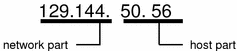
The bytes of the IP address are further classified into two parts: the network part and the host part.
Network Part
This part specifies the unique number assigned to your network. It also identifies the class of network assigned.
Host Part
This is the part of the IP address that you assign to each host. It uniquely identifies this machine on your network. Note that for each host on your network, the network part of the address will be the same, but the host part must be different.
Subnet Number (Optional)
Local networks with large numbers of hosts are sometimes divided into subnets. If you choose to divide your network into subnets, you need to assign a subnet number for the subnet. You can maximize the efficiency of the IP address space by using some of the bits from the host number part of the IP address as a network identifier. When used as a network identifier, the specified part of the address becomes the subnet number. You create a subnet number by using a netmask, which is a bit mask that selects the network and subnet parts of an IP address.
What is the Default Gateway?
A default gateway is a node that is present in the computer network that serves as a forwarding host to another network when the destination IP address of a packet does not match with any route.
Functions
The functions of default gateway are explained below −
The major function of the default gateway is to pass the information to another router when the current packet does not know the destination.
It is a node or a router in the network that connects the host to remote network components.
Whenever a packet needs to be transmitted to another network, the packet must pass through the default gateway and the default gateway identifies the destination route and forwards the packet on that route. It is considered as an exit point for the packets in the network.
Find PC’s default gateway IP address
You can find your PC’s default gateway IP address by following the steps given below −
1. By using the Command Prompt window, type “ipconfig” then press “Enter/Return” on your keyboard.
2. We can see a lot of information generated in this window.
3. Just scroll up and we can see “Default Gateway” with the device’s IP address (e.g., 192.168.255.1) listed to the right of it.
4. When a default gateway is not configured on a host, the packet will be dropped. Packet won’t leave the host at all. Default gateway should always be configured for the packet to reach the destination.
5. If default gateway is incorrectly configured, what situation may occur is explained below −
6. The host cannot communicate with other hosts in the local network.
7. The switch will not forward packets initiated by the host.
8. The host will have to use ARP to determine the correct address of the default gateway.
9. The host cannot communicate with hosts in other networks. A ping from the host to 168.0.0.1 would not be successful.
10. When a host needs to send a message to another host located on the same network it can forward the message directly.
11. When a host needs to send a message to a remote network, it must use the router also called as default gateway.
12. This is because the data link from the address of the remote destination on the host cannot be used directly.
13. Instead the IP packet has to be sent to the router and the router will forward the packet towards its destination.
What is “network ID” and “host ID” in IP Addresses?
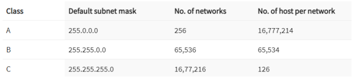
IP addresses are divided into 5 classes namely, Class A, Class B, Class C, Class D, and Class E. This concept came in around the 1980s. Where
Class A is generally used for big networks such as the ISP networks.
Class B is used for medium to large networks like some big organizations.
Class C addresses are generally used for smaller networks.
Class D addresses are used for Multicasting.
Class E addresses are reserved addresses and they are used for experimental purposes.


Binary to decimal conversion
To find decimal value of a number ,just add the numbers where true value occurs under the table values.ie,where 1 occur.

Decimal to Binary Conversion
To find the binary value, just check the octect can subtrated from the below table values, If yes ,put 1 or else 0.

NAT vs PAT difference
Network Address Translation (NAT) and Port Address Translation (PAT) both map IP addresses on an internal network to IP addresses on an external network. Which method of address translation you use depends on the types of networks that you are translating and the number of available IP addresses that you have.
If you are connecting a site in the 10.10.10.0 network to a site in the 10.10.20.0 network, you could use NAT to translate 10.10.10.0 IP addresses to available 10.10.20.0 IP addresses so that hosts on the 10.10.10.0 network can access data and use network resources on the 10.10.20.0 network. However, for this scenario to work, you must have an address pool that contains enough available IP addresses on the 10.10.20.0 network to accommodate every host on the 10.10.10.0 network, because NAT requires a one-to-one relationship when translating IP addresses.
PAT attempts to use the original source port number of the internal host to form a unique, registered IP address and port number combination. For example, two hosts that have been assigned the IP addresses 10.10.10.100 and 10.10.10.101, respectively, could send traffic to and receive traffic from the Internet by using the single public IP address 123.45.67.89. If that port number is already allocated, PAT searches for an available alternate source port number. Therefore, the host at IP address 10.10.10.100 could access the Internet by using the public IP address and source port combination of 123.45.67.89:10000. Meanwhile, the host at IP address 10.10.10.101 could access the Internet by using the IP address and source port combination of 123.45.67.89:10001.
If you are connecting a site in the 10.10.10.0 network to the Internet, you must translate host IPs on that network to a registered IP address that is routable over the Internet. In order to use traditional NAT in this scenario, you would need to purchase a registered IP address for each host on your internal network. Alternatively, you could use PAT to translate all the IP addresses on the internal network to a single, shared IP address that connects to the Internet. PAT, which is also known as NAT overloading, uses 16-bit source port numbers to map and track traffic between an internal host and the Internet.
As you can see, the first letter in each acronym denotes the difference between NAT (Network Address Translation) and PAT (Port Address Translation), which should make it easier for you to remember which does what. Just remember that both NAT and PAT use at least one IP address and that PAT is also referred to as NAT overloading because it uses one IP address for all clients to multiple ports, whereas standard NAT uses a one-to-one IP address relationship per client.
